Application Software Structure - Definitions
Modules to build up the Structure
Structure Overview
You normally write the PLC![]() "Programmable Logic Controller"
A Programmable Logic Controller, PLC, or Programmable Controller is a digital computer used for automation of industrial processes, such as control of machinery on factory assembly lines.
Used to synchronize the flow of inputs from (physical) sensors and events with the flow of outputs to actuators and events program. Whereas Kollmorgen application team members create in most cases the motion control
"Programmable Logic Controller"
A Programmable Logic Controller, PLC, or Programmable Controller is a digital computer used for automation of industrial processes, such as control of machinery on factory assembly lines.
Used to synchronize the flow of inputs from (physical) sensors and events with the flow of outputs to actuators and events program. Whereas Kollmorgen application team members create in most cases the motion control![]() Motion control is a sub-field of automation, in which the position and/or velocity of machines are controlled using some type of device such as a hydraulic pump, linear actuator, or an electric motor, generally a servo. Motion control is an important part of robotics and CNC machine tools; however, it is more complex than in the use of specialized machines, where the kinematics is usually simpler. The latter is often called General Motion Control (GMC). Motion control is widely used in the packaging, printing, textile and assembly industries part.
Motion control is a sub-field of automation, in which the position and/or velocity of machines are controlled using some type of device such as a hydraulic pump, linear actuator, or an electric motor, generally a servo. Motion control is an important part of robotics and CNC machine tools; however, it is more complex than in the use of specialized machines, where the kinematics is usually simpler. The latter is often called General Motion Control (GMC). Motion control is widely used in the packaging, printing, textile and assembly industries part.
The global software structure is built up with different modules placed on two different levels as showed on the figure below:
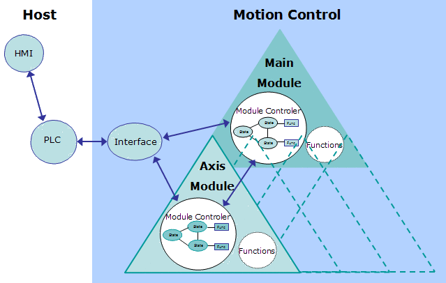
Figure 7-28: Software Structure Overview
Module Definition:
- A module is one unit of the software structure (triangle)
- It is controlled by one module from the next higher level and can in turn control several modules in the next lower level
- It never communicates with modules of the same level
- It can generally run independently from any other modules at the same or higher level
To have the structure running as a real application, it needs to be controlled by a PLC. As the PLC is not part of the application structure, only the main and axis modules are described here.
Main Module description
The main module controls the functional work that globally affect the application (e.g. multi axes functions). It receives commands from the PLC and sends back acknowledgements. The main module does not directly act on the physical axes, but controls the axis modules that are linked to them.
Communication between main and axis modules is done via internally defined data channels.
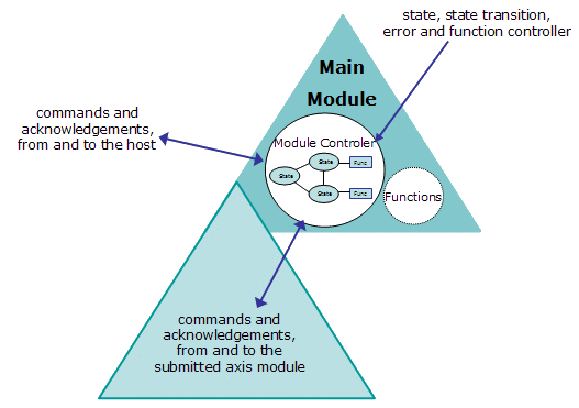
Figure 7-29: Main Module Description
As shown on the figure, the main module consists of two parts:
- the module controller part is responsible for state, state transition, error and functions handling. It receives state transition and function call commands from the host, performs all needed actions and sends back some acknowledgements. In case of an error it reacts by itself and sends a message to the PLC. If requested, it activates state transitions and functions in the axis modules, by sending commands to them and waiting for acknowledgement. The main module controller also manages the error status of the submitted modules and performs the needed actions.
- the functional part consists of all functionalities needed for the current application. These functions can be state dependant (e.g. multi axes functions) or state independent (e.g. increase a speed value).
Axis Module description
The axis module controls the functional work that affect the application one or more physical axes (e.g. single-axis functions). It receives commands from the PLC and sends back acknowledgements.
The axis module also communicates with its main module via the internally defined data channel.
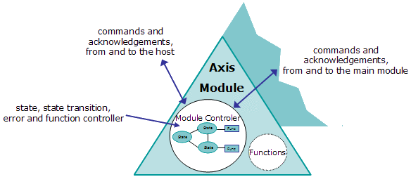
Figure 7-30: Axis Module Description
As shown on the figure, the axis module consists of the same two parts as the main module:
- the module controller part is responsible for state, state transition, error and functions handling. If the axis module is not connected to its main module, it receives state transition and function call commands from the host, performs all needed actions and sends back some acknowledgements. If connected, state transition commands are received from its main module and not from the host. In case of an error it only reacts by itself, if it is not connected to the main module.
- the functional part consists of all functionalities needed for the current physical axis. These functions can be state dependant (e.g. single axes functions) or state independent (e.g. increase a speed value).


